
A CNC MPG handwheel provides manual rotary input for a suitable control system during setup, jogging and position adjustment. Its use on a milling machine, lathe or router depends on the machine’s supported operating modes and receiving hardware. The handwheel generates signals; the controller selects the axis, interprets the input and applies the permitted motion behavior.
For a new panel installation or a replacement, start with that signal path. Confirm what the receiving board needs, how the operator will use the wheel, and which mechanical details the panel must accommodate. A familiar appearance or matching supply label is only part of the assessment. Start with the application overview, then compare the configuration specifications with the machine requirements.
Where the handwheel fits in a setup workflow
An operator may use handwheel input to approach a workpiece, prepare a work origin or make a controlled setup adjustment. The machine procedure determines when that input is enabled and what checks precede movement. A wheel connected to an input does not itself establish an operating mode or movement limit.
The handwheel body provides rotary channels and needs its own supply connections. Axis selectors, increment switches and enabling controls belong to the surrounding panel, pendant or control system. Emergency-stop functions follow the machine’s safety design and are separate from the handwheel’s A/B channels.
The receiving board detects the signals, while the controller or software interprets accepted counts. If the indicated response differs from expectations, the cause may involve decoding, scaling or mode settings as well as the physical part. See MPG signals, PPR and counts for the distinction between those quantities.
Milling machines and machining centers
On a supported milling machine or machining center, handwheel input can assist with fixture setup, tool approach and work-coordinate preparation. The controller associates the input with the selected axis. Tool offsets, coordinate systems and movement increments remain controller functions.
For installation planning, record the exact CNC model and the board or module that receives the handwheel channels. A controller family name may cover several input arrangements. The relevant board documentation should identify input format, thresholds, reference requirements and count settings.
Panel location also affects usability. Compare the 60 mm and 80 mm diameters with available space around nearby switches, the operator’s access and any enclosure door. Neither diameter establishes a different electrical interface or a guaranteed improvement in tactile response. Confirm the mounting pattern and rear terminal access before committing to a panel layout.
Lathes and position adjustment
A CNC lathe may accept handwheel input for setup-related position changes when its control system supports that mode. The operator must understand the selected axis, direction convention and displayed units before interpreting the response.
For a turning axis, the controller may display or apply settings using a diameter or radius convention. Consult the controller instructions rather than calculating travel from the handwheel’s PPR alone. A given number of received counts can lead to different requested movement when controller scaling changes.
Mechanical clicks, electrical cycles and decoded counts are separate. If a replacement must reproduce a particular response per click, compare detent behavior and waveform alignment as well as decoding and increment settings. PPR by itself does not establish a detent count. The requested movement increment also does not certify the complete machine’s positioning accuracy or repeatability.
Routers and engraving equipment
A router or engraving machine may use MPG input for work-origin setup and approach adjustments. In these systems, the receiving interface board, motion controller and software configuration can all influence the result. Any required software support must be checked for the actual installation.
The board documentation should state its accepted A/B input format, allowable electrical levels, timing limits and filtering behavior. A nominal 24 V handwheel supply does not establish a 24 V output signal or direct connection to a general-purpose digital input. The input must support the required counting behavior as well as the electrical interface.
Cable routing and connections are part of the machine design. Plan the signal path with the equipment’s wiring and EMC instructions, including shield bonding and reference connections. Terminal count alone cannot establish a permissible cable distance or resistance to interference in a particular machine environment.
Replacement and retrofit evaluation
Begin with the installed component’s model, voltage label, terminal markings and photographs of the connections. Identify the handwheel body separately from any complete pendant assembly. Record the receiving board and existing controller settings before comparing a replacement.
Check the handwheel output circuit and the board input circuit as separate items. Matching the supply voltage is necessary but does not demonstrate compatible signal levels, loading or timing. If an interface conversion is needed, its design requires confirmed specifications on both sides; it cannot be selected from terminal count alone.
Mechanical checks should include the body diameter, mounting-hole pattern, threads, panel opening and rear space. Similar dials may have different mounting details. Conversely, a shared dimension in two drawings does not establish that either part fits the same housing. Follow the panel mounting checks for a structured comparison.
The installation environment needs its own assessment. Exposure at the front panel and around the rear terminals depends on the enclosure and the selected version’s installation requirements. Do not infer coolant suitability or a complete assembly protection rating from the handwheel’s appearance or a general reference value.
Configuration checks before requesting a quote
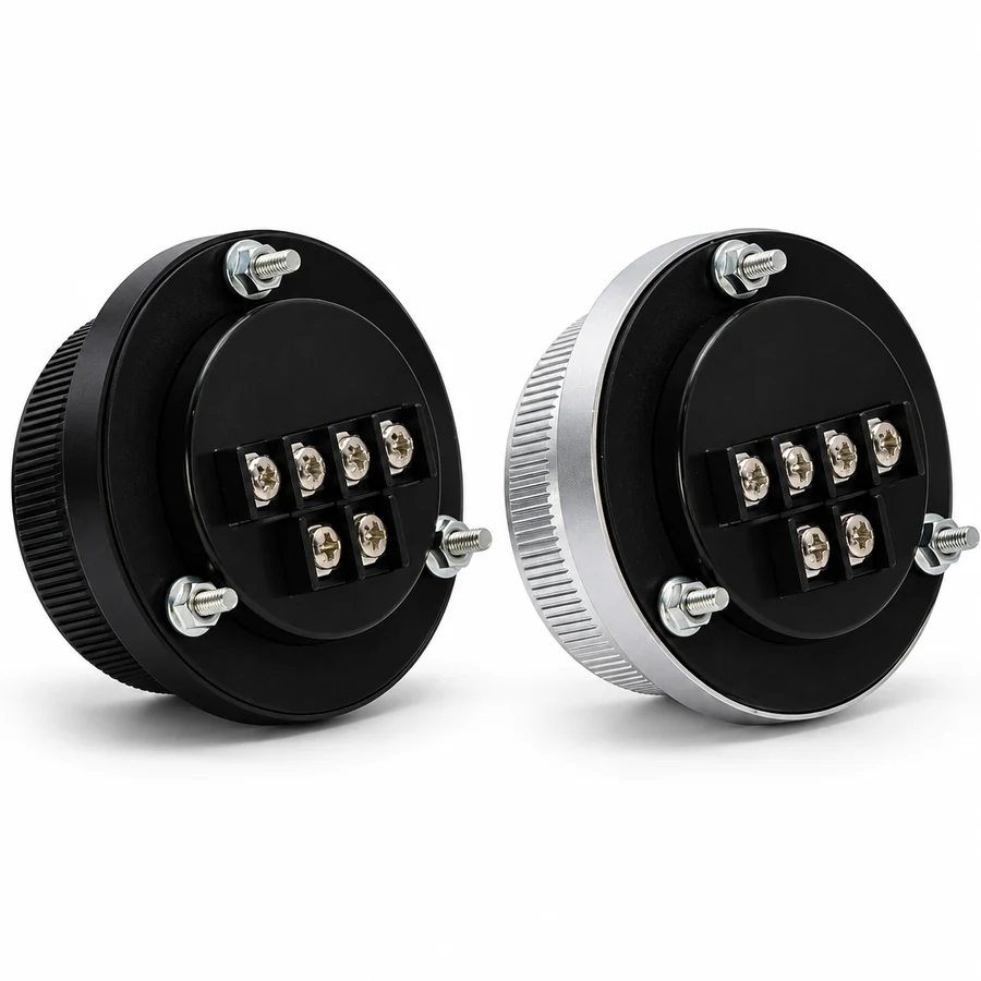
The listed CINKR panel-mount handwheels have 60 mm or 80 mm diameters and aluminum alloy bodies and dials with black or silver anodized finishes. Available configurations combine those choices with four or six terminals and the listed supply/PPR combinations. Review the available configurations alongside the receiving input requirements.
Electrical and mechanical information
The supply/PPR combinations are 5 V DC with 100 PPR, 12 V DC with 25 PPR, and 24 V DC with 100 PPR. Each is a configuration choice, rather than an operating point in one continuous voltage range. The stated supply does not determine the output circuit or signal level.
Record whether the installed unit has VCC, 0V, A and B labels, or also A- and B- labels. These identify supply and channel functions; they do not prove a particular electrical standard. Use the wiring preparation guide to prepare the interface questions.
For mounting, provide panel thickness, available rear depth and an existing panel drawing or measured hole pattern. Include room for conductors and access to the terminals, rather than assessing only the visible dial.
Controller and replacement details for an MPG quote
Send the preferred configuration and quantity with the controller and receiving board models through the request for quotation. Include relevant input specifications, old-part labels and installation dimensions. State which details are confirmed and which still need checking.
That information supports a focused review of the proposed handwheel against the application. Complete the mechanical and electrical comparison before treating a replacement as interchangeable, then follow the machine’s documented commissioning procedure to verify the installed response.