
A CNC MPG handwheel is a manual pulse generator: turning the wheel produces electrical signals that a suitable control system can interpret as manual input. It is also called a CNC electronic handwheel. In a supported operating mode, that input can help an operator jog an axis or make setup adjustments. The handwheel supplies information; the controller decides which axis responds, how much movement is requested and whether movement is permitted.
Understanding that division helps when comparing a new part or replacing an existing unit. Diameter, supply voltage and pulse count are useful starting points, but the receiving circuit and the mounting arrangement also need to match.
An electronic handwheel versus a mechanical handwheel
A mechanical handwheel transfers rotation through a physical connection, such as a shaft and lead screw. Its relationship to travel depends on the mechanism. An electronic MPG sends signals to receiving electronics instead. There is no fixed mechanical relationship between one wheel revolution and one axis movement.
The controller applies the selected axis, increment and operating mode to the input it receives. A rotary axis may use angular units, while a linear axis may use millimeters or inches. Changing a controller setting can change the requested movement without changing the handwheel.
The CINKR product discussed here is a panel-mount handwheel body. Its intended place in a panel or enclosure should be assessed separately from any switches, cable assembly or other controls needed for the complete machine installation.
A manual pulse generator is a manually operated incremental encoder used to provide operator input. A shaft encoder used for position feedback measures the rotation of a machine shaft. Their roles differ, and an MPG should not be treated as a substitute for a feedback encoder based only on PPR or A/B channel labels.
What A and B signals tell the receiver
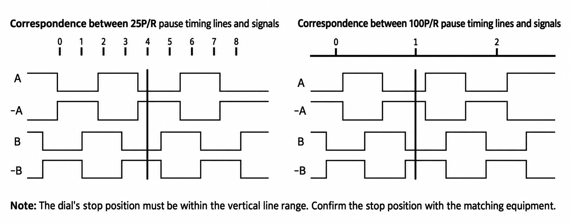
Incremental rotary inputs commonly use two channels, A and B. In quadrature operation, their waveforms are offset by approximately 90 electrical degrees. This phase relationship refers to an electrical cycle, rather than a quarter turn of the wheel. The sequence allows a suitable receiver to distinguish rotation direction as well as count events.
The receiver must accept the actual output circuit and signal levels of the selected handwheel. Input thresholds, loading, reference connections and timing requirements matter alongside the channel names. A label such as A does not describe all of those electrical properties.
Four-terminal configurations have VCC, 0V, A and B markings. Six-terminal configurations also have A- and B- markings for complementary channels. Terminal count alone does not establish a particular output circuit, logic voltage or interface standard. Read the terminal and wiring preparation guide before choosing an interface.
PPR, detents and decoded counts are different quantities
Pulses per revolution, or PPR, describes the electrical cycle count using the stated measurement convention. For the examples below, assume that PPR means complete cycles of one channel per mechanical revolution and that a matching quadrature receiver counts the indicated edges correctly.
| Rated PPR | ×1 counts per revolution | ×2 counts per revolution | ×4 counts per revolution |
|---|---|---|---|
| 25 | 25 | 50 | 100 |
| 100 | 100 | 200 | 400 |
Under those assumptions, ×1 decoding counts one event per cycle, ×2 counts two, and ×4 counts four. Controller documentation may use different terms for pulse counts or resolution, so compare definitions before transferring a setting from an old unit.
Detents are mechanical positions that the operator feels while rotating the wheel. Their number and their alignment with the waveform are separate specifications. A 100 PPR rating does not establish 100 detents or one accepted controller count per click. If click-by-click response matters, request confirmation of the detent behavior for the selected version and check the controller’s decoding settings.
How the controller determines a movement increment
For a controller operating in a simple position-increment mode, the assumed relationship is:
Commanded travel per revolution = effective decoded counts per revolution × configured increment per count
For example, 100 effective counts per revolution at 0.001 mm per count requests 0.1 mm of travel. With 400 effective counts and the same increment, the request becomes 0.4 mm. This example assumes that every count is accepted and that the controller uses the stated scaling directly.
These numbers describe commanded travel, not measured positioning accuracy. Actual movement depends on the complete machine, including its control settings, drive system and mechanics. Some systems apply filtering, limits or a velocity-related handwheel mode, so their response may require a different explanation.
PPR also does not define a maximum hand rotation speed by itself. The generated signal rate rises with rotational speed, and both the output and receiving input must support the resulting timing. Check permissible frequency and minimum pulse width rather than assuming a higher count always produces a better response.
The bare handwheel and a complete MPG pendant
A complete pendant can include a handwheel, enclosure, cable, axis selector, increment switch and enabling controls. Depending on the machine design, emergency-stop contacts may also be part of that assembly. These functions have separate connections and requirements.
The four or six terminals on the handwheel include its supply connections as well as rotary signal channels. They do not provide all the functions of a complete pendant. Replacing the handwheel body therefore requires identifying it separately from the surrounding switches and wiring.
For an existing installation, record the old component’s label, terminal markings and mounting dimensions, together with the receiving board model. A similar-looking dial does not establish interchangeability. The applications and replacement guide explains how those checks differ across machine workflows.
Available configurations and selection checks
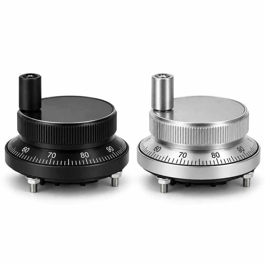
The listed CINKR configurations use 60 mm or 80 mm diameters, with an aluminum alloy body and dial in black or silver anodized finishes. Four-terminal and six-terminal options are available. Compare the current configuration list with the mechanical and electrical requirements of the installation. The dimension and signal illustrations provide a reference for the features being compared.
Supply and pulse-count combinations
The supply and pulse-count combinations are 5 V DC with 100 PPR, 12 V DC with 25 PPR, and 24 V DC with 100 PPR. These are separate supply configurations. They do not describe one unit accepting a continuous 5–24 V range, and changing supply voltage is not a way to select a different PPR.
Supply voltage also does not establish output signal level or direct compatibility with a controller input. The selected version’s output circuit and signal levels need confirmation against the receiving board documentation.
Information to prepare for an inquiry
For a configuration inquiry, provide the required diameter, finish, supply/PPR combination, terminal count and quantity. Include the controller and receiving board models, their electrical input requirements, and any available old-part documentation.
For the mechanical check, provide panel thickness, available rear space and the existing hole pattern. Use the mounting guide to distinguish body diameter, pitch circle and panel opening. Those details make a configuration review more useful than selecting on appearance or nominal voltage alone.