
An MPG handwheel panel cutout must be established from the complete mounting information for the selected version. Body diameter, mounting-hole pitch circle, hole size and a labeled inner circle describe different features. None should be substituted for the required panel opening without confirmation from the relevant drawing.
The listed CINKR handwheels have 60 mm and 80 mm body options. This guide compares the dimension callouts shown for those sizes and explains the panel information needed for installation or replacement. Use the original drawings in the technical details alongside these checks, including their views and callouts, before preparing a panel.
60 mm vs 80 mm handwheel mounting dimensions
The drawings show the following values. Dimensions are in millimeters. This comparison records the illustrated geometry; it is not a panel machining specification or a statement that the two versions share an enclosure.
| Drawing item | 60 mm body | 80 mm body |
|---|---|---|
| Body outer diameter | Φ60 | Φ80 |
| Mounting-hole pitch circle | Φ50.8 ±0.1 | Φ72 ±0.1 |
| Illustrated inner circle | Φ42 | Φ42 |
| Three hole callout | 3 × Φ3.5 | 3 × Φ4.5 |
| Rear thread / screw callout | 3 × M3 | 3 × M4 |
The outer diameter describes the body envelope in that view. It helps establish the space required on the panel face, including clearance from adjacent switches, panel edges and enclosure features. It does not identify the diameter of the opening behind the body.
Both drawings include Φ42. A shared inner-circle dimension does not prove a shared panel opening, locating feature or interchangeable housing. Identify the feature in the original view and confirm its relationship to the mounting surface before using it in a panel design.
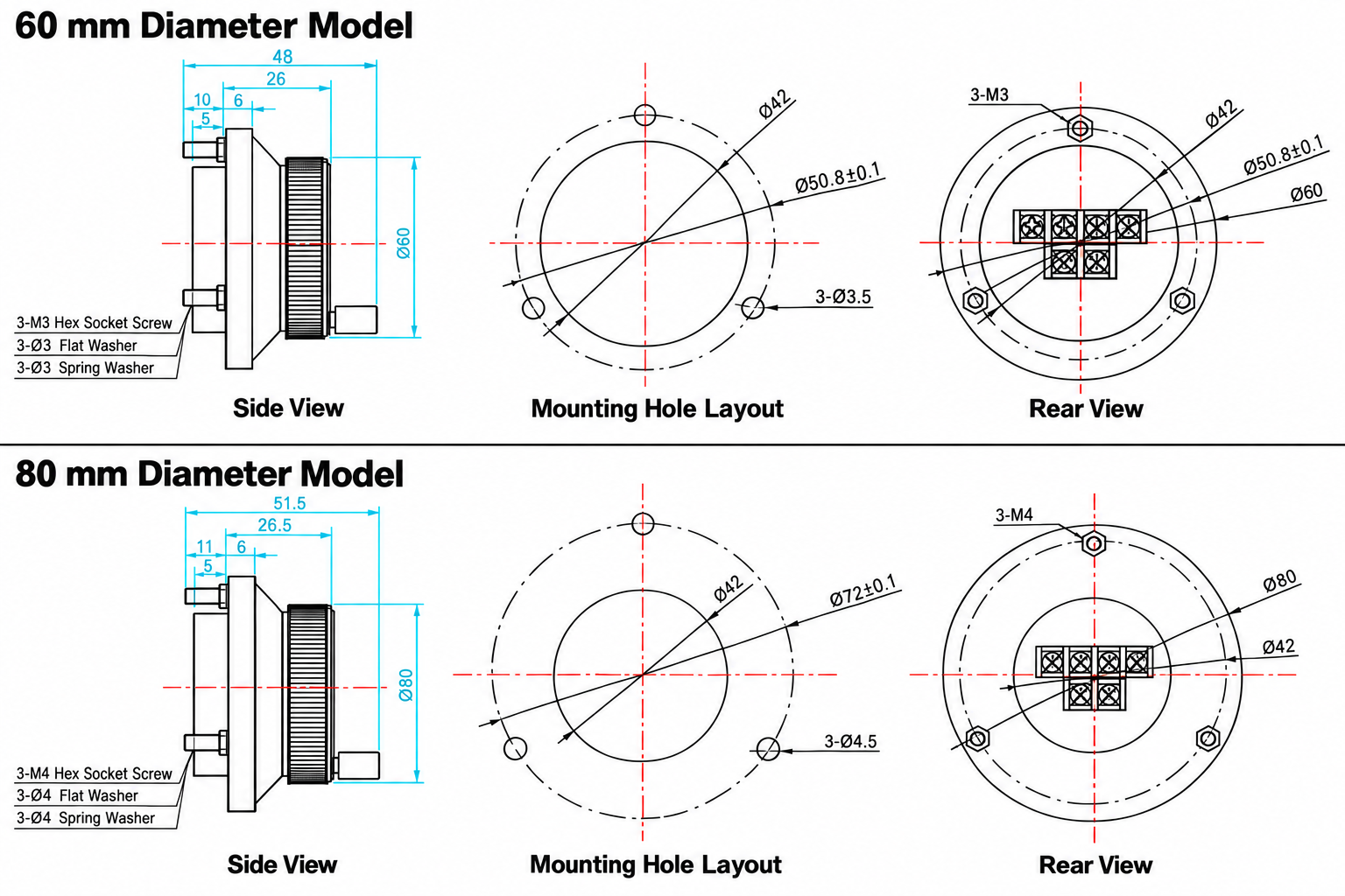
Pitch circles, holes and threads are separate dimensions
A pitch circle, often abbreviated PCD, is an imaginary circle passing through the centers of the mounting holes. Its diameter describes where those centers lie. Hole orientation and angular placement are additional parts of the pattern, so the PCD alone does not fully locate every hole on a panel.
Do not measure between two holes and treat the result as the PCD. That measurement is a chord between two centers. For three equally spaced holes, the chord between adjacent centers differs from the pitch-circle diameter. Establish the circle using the complete drawing or a suitable geometric measurement method, and verify the equal-spacing assumption before using it.
A callout such as Φ3.5 or Φ4.5 describes a hole diameter. M3 and M4 describe metric thread or screw sizes. They answer different questions: a clearance hole is not a threaded hole, and a screw diameter is not a panel opening. Match each callout to the feature and view it actually labels.
The illustrated PCD tolerance is ±0.1 mm for both sizes. Do not extend that tolerance to every other feature. The complete drawing must establish the other dimensions, applicable tolerances and mating relationships needed for fabrication.
Establishing the actual panel opening
Before cutting a new panel, identify which part of the assembly passes through the panel and which surfaces locate or support it. Use the selected version’s mounting information to establish the required opening shape, dimensions and tolerances. A circle shown inside a front or rear view may describe a body feature rather than the cutout.
A larger pitch circle does not necessarily require a larger central opening. It places the fixing points farther from the center, but the central clearance requirement depends on the component geometry. Likewise, sharing Φ42 does not establish that the 60 mm and 80 mm bodies can be exchanged without panel changes.
Keep the panel opening and the fixing pattern as separate entries in your panel drawing. Confirm their common reference and orientation so that a correctly sized opening is not combined with a rotated or misplaced hole pattern. If the available drawing does not settle a feature, request clarification before machining.
Panel thickness, rear depth and terminal access
Panel thickness affects the fastening arrangement. Confirm how the selected handwheel is retained and which screw length or engagement is required. Account for any specified washers, spacers or sealing components using the installation information for that version. Do not assume a particular gasket or compression allowance from the front appearance.
Available rear depth is measured from the actual panel mounting plane to the nearest obstruction. The assembly needs space for its rear features, terminals and connected conductors. A drawing’s overall height may include front projection or use a different reference plane, so it should not automatically be treated as an approved behind-panel installation depth.
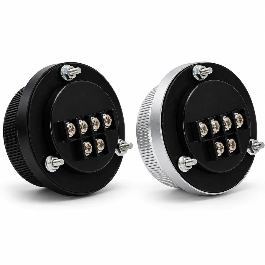
Terminal access needs more than static clearance. Allow space to identify markings, connect conductors and service the connection using the relevant installation requirements. Include cable bend space and nearby equipment when assessing the enclosure. Four-terminal and six-terminal arrangements should be checked for the selected version rather than inferred from an old connector.
Front-panel exposure and rear-enclosure conditions also require review. The completed installation’s protection depends on the enclosure, interfaces and version-specific requirements. This dimensional comparison does not establish an environmental rating or suitability for exposure to coolant or mist.
Checking an existing installation before replacement
Compare the existing component, panel and proposed replacement separately. A matching visible diameter can conceal differences behind the panel, while a matching electrical configuration does not establish mechanical fit.
- Record the old part’s model, body diameter and mounting orientation. Photograph the front and rear arrangements where accessible under the machine’s maintenance procedure.
- Document the actual panel opening independently of any inner circle on the component drawing. Record its shape, dimensions and locating features.
- Establish the mounting pattern from all hole centers and the drawing references. Identify hole diameters and threads without treating a two-hole chord as a PCD.
- Measure panel thickness and rear space from a stated reference plane. Include nearby obstructions, terminal access and cable bend requirements.
- Compare the complete selected-version drawing with those records. Resolve missing tolerances or uncertain features before assuming a direct replacement.
Electrical suitability remains a separate check. Record the supply marking, terminal labels and receiving board model, then use the wiring preparation guide to prepare the interface comparison. The application guide places those checks in the wider replacement workflow.
What to send with a mounting inquiry
For a configuration inquiry, provide the preferred 60 mm or 80 mm diameter, finish, terminal count, supply/PPR combination and quantity. Include the panel drawing or existing hole-pattern measurements, panel thickness, available rear space and any unresolved mounting feature.
The listed supply/PPR combinations are 5 V DC with 100 PPR, 12 V DC with 25 PPR, and 24 V DC with 100 PPR. Black and silver anodized finishes are available for the aluminum alloy body and dial. See the configuration list for the current choices.
Use confirmed mounting information for the supplied version to finalize the panel. The purpose of the comparison is to identify the dimensions that must agree, so a shared number or similar appearance does not become an unsupported fit assumption.