Aluminum alloy dial and body
An aluminum alloy dial and body with a Black or Silver anodized finish give the handwheel a coordinated metal appearance. Choose the finish that complements your machine’s operator panel.

A CNC manual pulse generator converts handwheel rotation into A/B signals for a matching control system. This panel-mount CNC electronic handwheel is available in 60 or 80 mm, Black or Silver, with 4 or 6 terminals. Compare the supply/PPR configurations and mounting dimensions for your installation.
The handwheel provides signals. Axis selection, jog mode, movement increments and motion behavior are implemented by the control system.
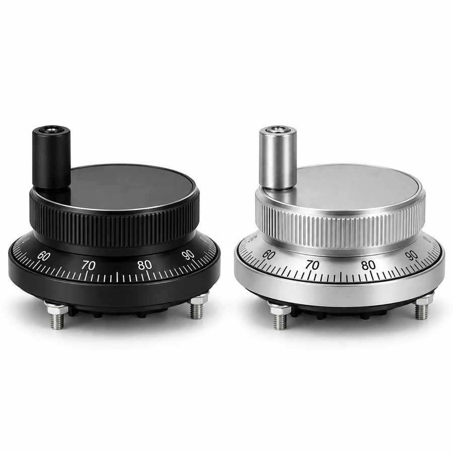
Compare the front, scale ring and rear arrangement. Select any image for a larger view.
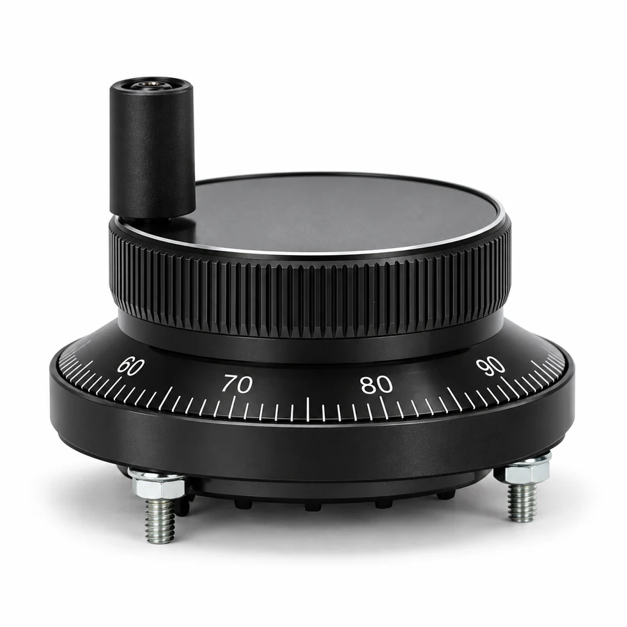
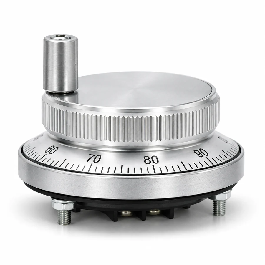
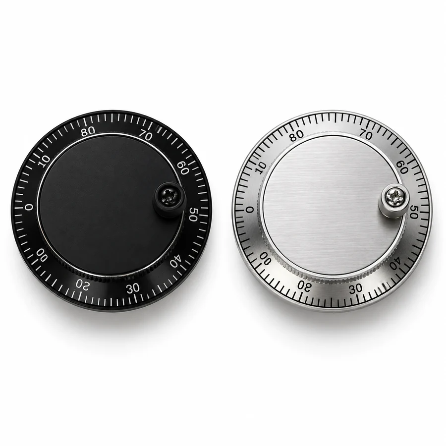
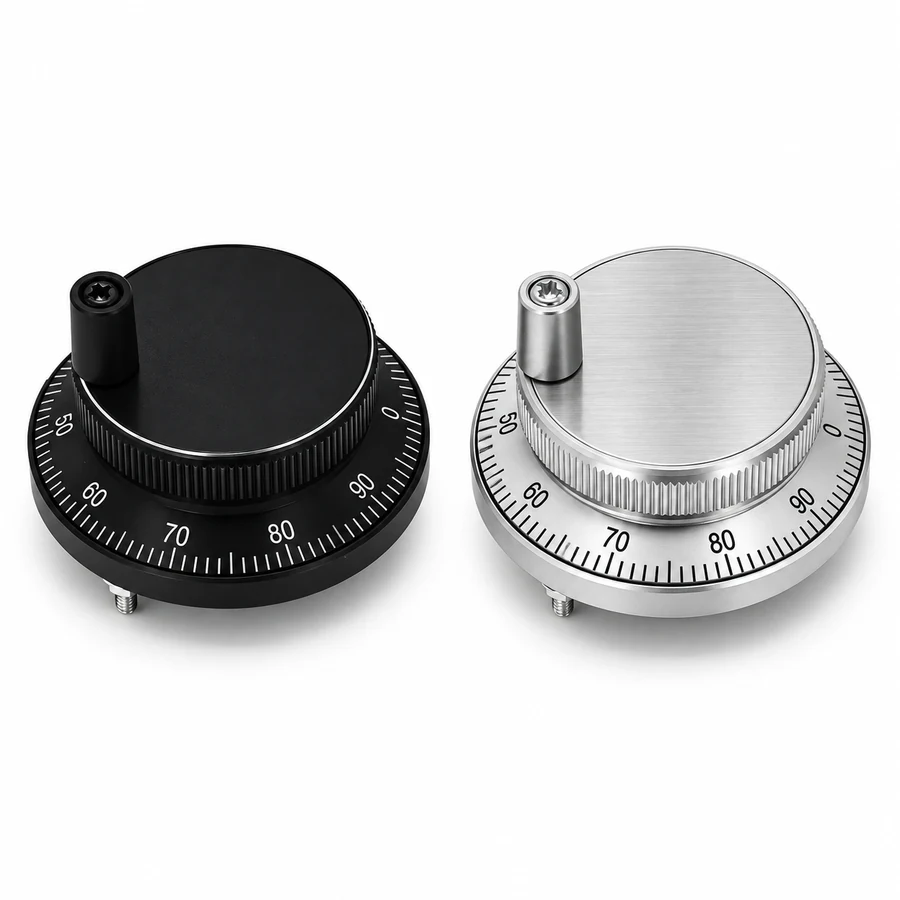
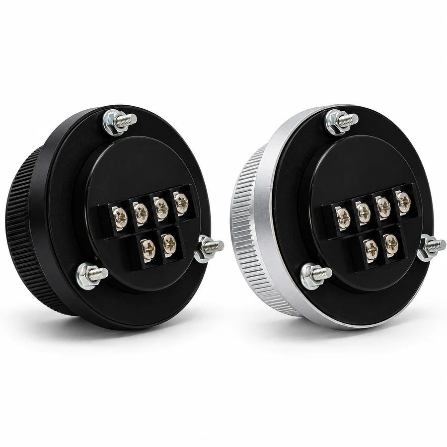
An aluminum alloy construction, numbered scale ring and panel-mount format bring the essential details together. Choose the finish and configuration that suit your operator panel and receiving interface.
An aluminum alloy dial and body with a Black or Silver anodized finish give the handwheel a coordinated metal appearance. Choose the finish that complements your machine’s operator panel.
The numbered scale ring gives a visual reference as you turn the front handle during setup and position adjustment. Rotary input becomes A/B signals for the controller to interpret at the selected movement increment.
Two body diameters let you plan around the available panel space. Compare the front profile, mounting pattern and rear terminal access to select the arrangement that fits your enclosure design.
Choose a supply/PPR version and terminal count alongside body size and finish. The offered combinations are 5 V / 100 PPR, 12 V / 25 PPR and 24 V / 100 PPR. For a replacement, use the existing unit’s labels and mounting dimensions together with the receiving board details to define the required configuration.
Explore configurations, or request a specification and quotation for your installation.
Choose body size, finish, nominal supply and terminal count from 24 configurations. Each supply version has its own PPR.
These are separate supply/PPR versions, available across both terminal counts, diameters and finishes. A unit is powered at its selected nominal voltage. Match its output circuit and signal levels to the receiving interface specification.
No options selected
Select the options that apply to your machine.
| Color | Diameter | Supply | Terminals | PPR | Select |
|---|---|---|---|---|---|
| Black | 60 mm | 5 V DC | 4 | 100 PPR | Select |
| Black | 60 mm | 5 V DC | 6 | 100 PPR | Select |
| Black | 60 mm | 12 V DC | 4 | 25 PPR | Select |
| Black | 60 mm | 12 V DC | 6 | 25 PPR | Select |
| Black | 60 mm | 24 V DC | 4 | 100 PPR | Select |
| Black | 60 mm | 24 V DC | 6 | 100 PPR | Select |
| Black | 80 mm | 5 V DC | 4 | 100 PPR | Select |
| Black | 80 mm | 5 V DC | 6 | 100 PPR | Select |
| Black | 80 mm | 12 V DC | 4 | 25 PPR | Select |
| Black | 80 mm | 12 V DC | 6 | 25 PPR | Select |
| Black | 80 mm | 24 V DC | 4 | 100 PPR | Select |
| Black | 80 mm | 24 V DC | 6 | 100 PPR | Select |
| Silver | 60 mm | 5 V DC | 4 | 100 PPR | Select |
| Silver | 60 mm | 5 V DC | 6 | 100 PPR | Select |
| Silver | 60 mm | 12 V DC | 4 | 25 PPR | Select |
| Silver | 60 mm | 12 V DC | 6 | 25 PPR | Select |
| Silver | 60 mm | 24 V DC | 4 | 100 PPR | Select |
| Silver | 60 mm | 24 V DC | 6 | 100 PPR | Select |
| Silver | 80 mm | 5 V DC | 4 | 100 PPR | Select |
| Silver | 80 mm | 5 V DC | 6 | 100 PPR | Select |
| Silver | 80 mm | 12 V DC | 4 | 25 PPR | Select |
| Silver | 80 mm | 12 V DC | 6 | 25 PPR | Select |
| Silver | 80 mm | 24 V DC | 4 | 100 PPR | Select |
| Silver | 80 mm | 24 V DC | 6 | 100 PPR | Select |
Configuration options and series design references for the CNC MPG handwheel.
Choose color, diameter, supply version and terminal count. PPR is tied to the supply version, as listed below; 4 or 6 refers to terminal count, not the number of machine axes.
| Parameter | Options / rule | Unit |
|---|---|---|
| Color | Black, Silver | — |
| Diameter | 60, 80 | mm |
| Nominal supply | 5, 12, 24 | V DC |
| Terminal count | 4, 6 | terminals |
| PPR | 5 V: 100; 12 V: 25; 24 V: 100 | PPR |
Typical values for the series at the stated conditions. The order drawing governs the supplied version.
| Parameter | Design reference | Unit | Notes |
|---|---|---|---|
| Supply tolerance | ±5% | V DC | Specified for the 5 V DC configuration. |
| High / low signal level | High > 85% VCC; low < 0.3 V | V | Output levels under the rated load. |
| Current consumption | < 100 | mA | Typical consumption at the rated supply. |
| Response frequency | 0–20 | kHz | Response range of the output stage. |
| Waveform | Square wave | — | A/B quadrature output. |
| Starting torque at +25 °C | 1 × 10⁻² | N·m | Measured at the stated temperature. |
| Vibration reference | 50 | m/s² | 10–200 Hz, X, Y and Z axes, 2 h each. |
| Shock reference | 980 | m/s² | 6 ms, X, Y and Z axes, two cycles each. |
| Ingress protection | IP54 equivalent | IP | Front dial assembly with its perimeter gasket. The rear connection area sits outside the sealed zone. |
| Operating temperature | −10 to +70 | °C | Ambient operating range. |
| Storage temperature | −30 to +85 | °C | Storage and transport range. |
| Humidity | 30–85, non-condensing | % RH | Non-condensing operation. |
| Weight | 0.2–0.3 | kg | Varies with diameter and terminal count. |
| Material | Aluminum alloy | — | Dial and body, with Black or Silver anodized finish. |
Dimension and signal illustrations for the 60 mm and 80 mm handwheel bodies.
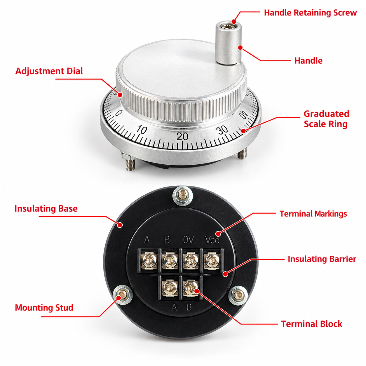
The handle, scale ring, mounting posts and terminal area are identified in this overview.
The rear view shows the mounting posts and the terminal area of a six-terminal unit.
Side, mounting-hole and rear views of the 60 mm and 80 mm bodies. All dimensions are in millimeters.
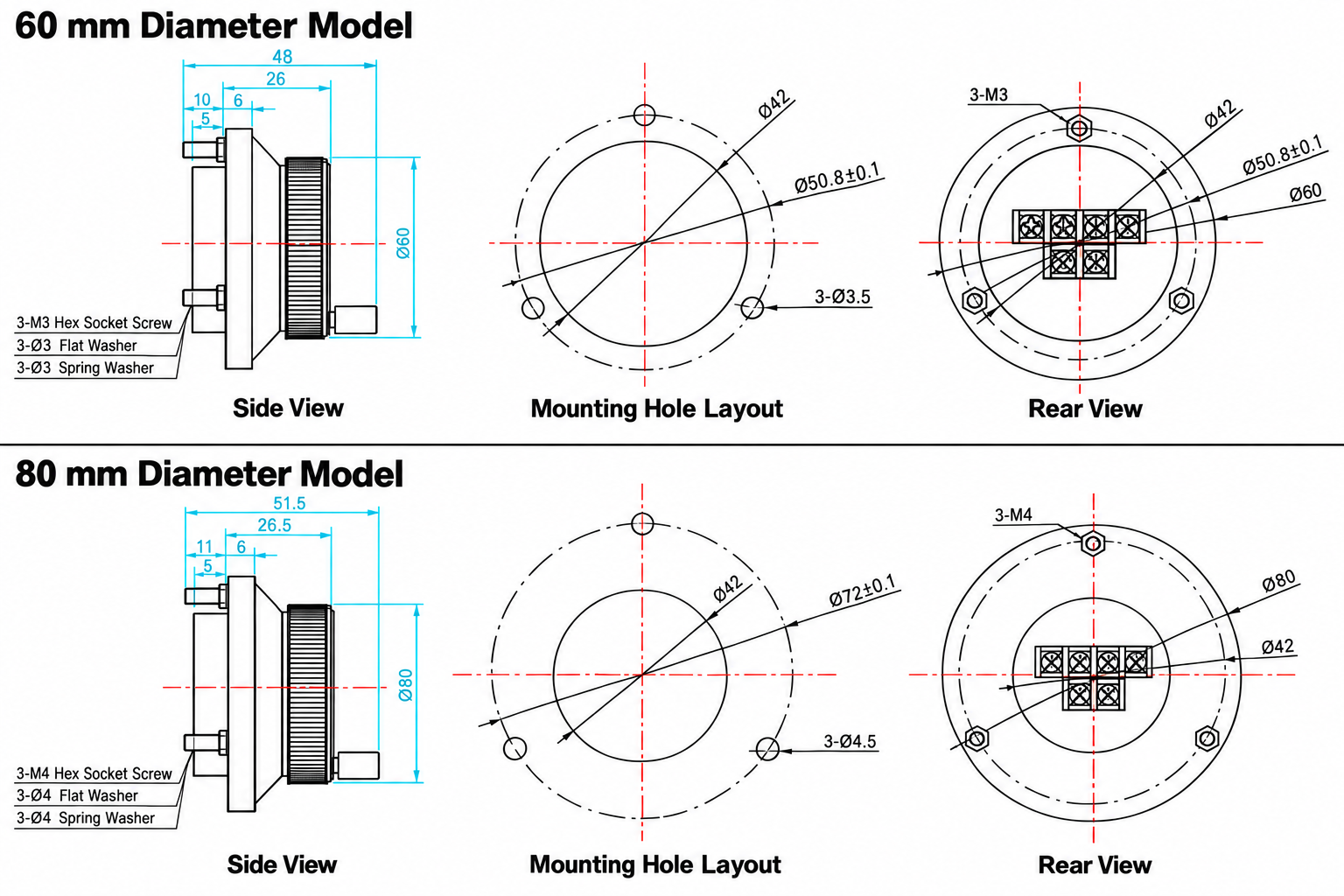
| Illustrated dimension | 60 mm drawing | 80 mm drawing |
|---|---|---|
| Outer diameter | Φ60 | Φ80 |
| Overall side span shown | 48 | 51.5 |
| Other side dimensions shown | 26; 10; 6; 5 | 26.5; 11; 6; 5 |
| Mounting-hole pitch circle shown | Φ50.8 ±0.1 | Φ72 ±0.1 |
| Inner circle dimension shown | Φ42 | Φ42 |
| Three mounting holes | 3 × Φ3.5 | 3 × Φ4.5 |
| Rear thread / screw callout | 3 × M3 | 3 × M4 |
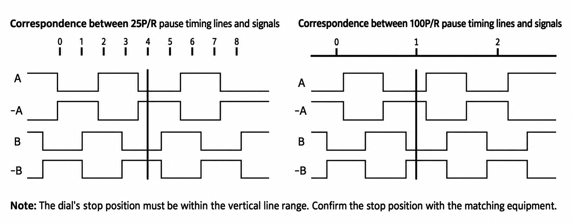
A/B phase sequence allows a matching receiver to distinguish rotation direction. With PPR taken as complete cycles per phase per revolution, 25 PPR corresponds to 25 / 50 / 100 counts at ×1 / ×2 / ×4 decoding, and 100 PPR corresponds to 100 / 200 / 400 counts.
Mechanical detents are separate from electrical cycles. Commanded travel per revolution is the effective decoded count multiplied by the increment the controller assigns to each count, so PPR alone does not define positioning accuracy.
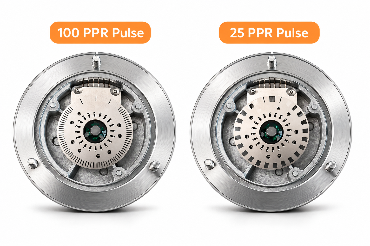
The internal views illustrate the difference between the two pulse-count examples. The internal section is schematic and does not establish the construction of every supplied configuration.
PPR describes electrical cycles under the stated convention. Commanded movement and machine positioning depend on the receiving system, controller parameters and machine mechanics.
Four-terminal models provide VCC, 0V, A, B. Six-terminal models add A-, B- as complementary channels; the trailing minus marks the inverted phase and does not denote a negative power connection.
Supply voltage, output circuit and signal levels are separate electrical characteristics. Compare the handwheel specification with the receiving board documentation. See the 4-terminal and 6-terminal wiring guide for the information to collect.
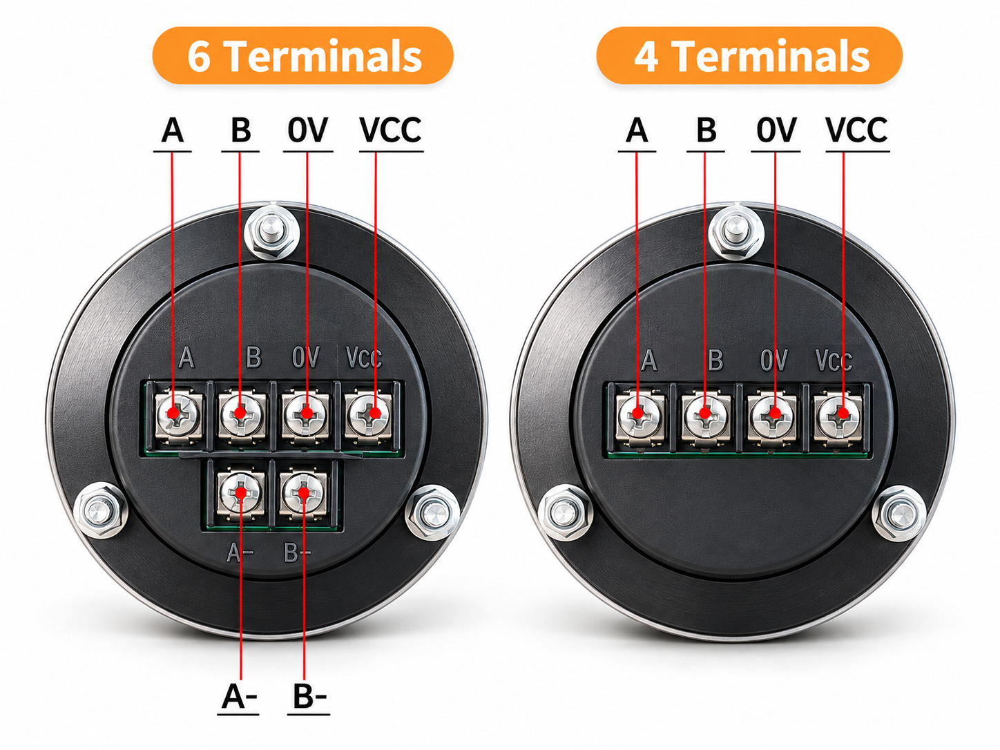
Both terminal counts carry VCC, 0V, A and B. The six-terminal block adds the complementary pair marked A- and B-, which identifies the complementary signals without establishing a particular electrical standard. In the illustrated view, the six-terminal block has the four common positions on the upper row and A- and B- on the lower row; the four-terminal block has a single row. Use the selected unit’s labels and drawing for the physical connection order.
| Terminal | Carries | Phase relationship | Fitted on |
|---|---|---|---|
| VCC | Positive supply connection | DC, nominal 5 / 12 / 24 V by configuration | Both counts |
| 0V | Supply return | Common to the encoder | Both counts |
| A | Quadrature phase A | Leads or lags B by 90° | Both counts |
| B | Quadrature phase B | Leads or lags A by 90° | Both counts |
| A- | Complementary phase A | Inverted phase, read against A | Six-terminal only |
| B- | Complementary phase B | Inverted phase, read against B | Six-terminal only |
The drawings identify a three-position mounting pattern. Pitch-circle diameter, hole diameter, thread size and the Φ42 inner circle describe different features; none alone defines the complete panel cutout. The values below preserve the drawing annotations.
| Mounting item | 60 mm body | 80 mm body |
|---|---|---|
| Body outer diameter | Φ60 | Φ80 |
| Mounting-hole pitch circle | Φ50.8 ±0.1 | Φ72 ±0.1 |
| Inner circle dimension | Φ42 | Φ42 |
| Three mounting holes | 3 × Φ3.5 | 3 × Φ4.5 |
| Rear thread / screw callout | 3 × M3 | 3 × M4 |
Include panel thickness, rear space and terminal access with your inquiry. Use the mounting and panel cutout guide to distinguish the dimensions needed for your panel layout.
The handwheel provides rotary signals. Machine controls, interface hardware and configured parameters determine the permitted operation.
Manual rotary input during fixture setup, work-coordinate preparation and tool approach. On a planned installation the CNC model and the board or module receiving the MPG signals determine the interface, together with the electrical thresholds and counter settings. Compare 60 mm and 80 mm body dimensions against the space, mounting pattern and access available on the operator panel.
Rotary input for controlled position changes during setup where the control system provides that mode. Axis direction, the diameter or radius display convention and the increment settings are held by the CNC, and movement per physical detent follows from its decoding together with the wheel’s stop-position waveform — so a replacement is matched on those parameters as well as on nominal supply voltage.
Position input for work-origin setup and approach adjustments where the interface board supports matching MPG signals. The board, motion controller, software and any plugin or configuration are all part of the signal path, and the board’s documented input specification is the reference for whether it can receive the handwheel’s A/B channels.
Replacement work begins with the existing panel-mount unit: its model, voltage marking, terminal labels and physical dimensions go with the controller details rather than with the machine’s outer brand label. Two handwheels of similar appearance can use different output circuits, and matching electrical labels can sit on different hole patterns or rear clearances — so the full specifications decide interchangeability.
Axis selection, enabling controls, emergency stops and increment switches are functions of the machine control system. Read the application and replacement guide for a practical selection checklist.
Answers on configuration, mounting, enclosure protection and controller matching.
Choose a 60 mm or 80 mm aluminum alloy handwheel with a Black or Silver anodized finish and 4 or 6 terminals. The supply/PPR configurations are 5 V DC with 100 PPR, 12 V DC with 25 PPR, and 24 V DC with 100 PPR.
The available versions are 5 V DC / 100 PPR, 12 V DC / 25 PPR and 24 V DC / 100 PPR, across both terminal counts, diameters and finishes. These are separate supply configurations, not one wide-voltage unit. Changing the applied voltage does not select a different PPR.
Four-terminal models use VCC, 0V, A and B. Six-terminal models add complementary channels marked A- and B-. Terminal count alone does not specify the electrical output standard, signal levels or cable distance. Match the selected handwheel output specification to the receiving board requirements.
Tell us the controller model and the receiving board or module. Input compatibility depends on the output circuit, the signal levels, the A/B decoding setting and the rated pulse frequency of the counter.
No. PPR is the electrical cycle count per revolution. Mechanical detents, decoded counts, the commanded increment and machine positioning accuracy are separate, and the controller parameters together with the machine mechanics determine commanded travel.
The 60 mm body uses a Φ50.8 mm mounting pitch circle with 3 × M3 threads; the 80 mm body uses Φ72 mm with 3 × M4. Both drawings show a Φ42 mm inner circle; that dimension alone does not define a panel cutout. Include panel thickness, hole layout and available rear space with your inquiry.
Plan the panel and enclosure around the selected version and the actual exposure to dust, moisture and machine fluids. The series reference table does not establish a whole-machine protection rating. Rear terminals need an enclosure arrangement appropriate to the installation.
This product is a panel-mount MPG handwheel with a dial, scale ring and terminal block. Axis selectors, multiplier switches, enabling switches, emergency stops and cabling are not part of the handwheel configuration shown here. Plan those functions as part of the machine control system.
Use the quote request form to send your required configuration (color, diameter, supply/PPR and terminal count), quantity and destination. These details help us prepare a quotation for your requirements. Include the controller model and receiving board or module for the interface assessment. For replacements, add the old part model, terminal labels and mounting dimensions.
CINKR supplies panel-mount CNC MPG handwheels for new installations and replacement assessment. Choose the required configuration and send your controller and receiving-board details with your inquiry.
Your inquiry is prepared in your browser and sent from your own email application. Privacy details
No options selected
Clear guidance on manual pulse generator signals, decoding counts, and machine tool integration.
Learn how a CNC MPG handwheel sends A/B signals, how PPR differs from detents and decoded counts, and what to check before selecting a unit.
Read GuideExplore CNC MPG handwheel use in milling, turning and routers. Review controller input, mounting and replacement checks before requesting a quote.
Read GuideCompare 60 mm and 80 mm MPG handwheel mounting dimensions. Identify pitch circles, hole sizes and the panel details needed before ordering.
Read GuideCompare 4-terminal and 6-terminal MPG handwheel markings. Check supply, A/B channels and receiver requirements before choosing a configuration.
Read Guide